-
Description
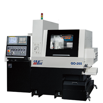
Simultaneous complex machining with main and back spindle!
More innovative features available- Larger bar capacity (Ø26mm)
- Higher rigidity
- Powerful spindle motors
- Greater tooling layout choices
Machine specification
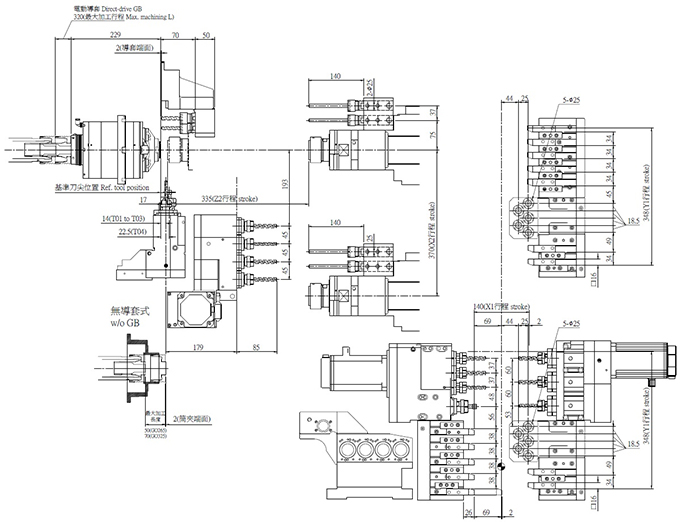
Model GO-265 Machining capacity Main spindle Bar stock diameter Ø8~26 mm [min. Ø3mm (OP.) (※1)] Machining length 320mm (Direct- drive guide bushing)
50mm (Guide bushing-less)
115mm (Mechanical-drive rotary guide bushing)Drilling Ø12 mm Tapping M10 Deep hole drilling Ø10mm Back spindle Working chuck diameter Ø26 mm Drilling Ø10 mm Tapping M8 Tool spindle spindle Drilling / tapping (Left cross tool) Ø8mm / M6 Drilling / tapping (Right cross tool) Ø8 mm / M6 Drilling / tapping (Back tool) Ø8 mm / M6 Slitting saw Ø45 mm ( Right cross tool T04) Max. speed Main spindle 10,000RPM Back spindle 10,000RPM Direct-drive guide bushing 10,000RPM Tool spindle 5,000RPM Tool size OD tool shank 16 × 16 × 100 mm Boring tool shank (For face/back ID tool or back tool post ) Ø25 mm Chuck for left cross tools ER16 × 3 ; ER20 × 1 Chuck for right cross tools ER16 Chuck for back live tools ER16 Chuck for back fixed tools ER16 (OP. : ER20) Chuck for deep hole drill ER16 Tool position No. (Max. mountable tool No.): 25 ( 32 ) Left OD turn tool post 5 Right OD turn tool post 2 (OP. : 7) Front/back ID tool post (one-body) 5 Back tool post 4 Left cross tool post 4 Right cross live tool post 3 Face deep drill 2 Motor Main spindle 3.7 / 7.5 KW ( Rated / 10% ) Back spindle 2.2 / 3.7 KW ( Rated/ 10 min.) Left cross tool 1.0 KW Right cross tool 1.0 KW Back tool 1.0 KW Direct-drive rotary guide bushing 2.2 / 3.7 KW (Rated/ 10 min.) X1, Y1, Z1, X2, Z2 axis 0.75 KW Coolant pump 0.75 KW Lubricating pump 0.011 KW Axis travel X1 142mm Y1 348mm Z1 320mm (Direct-drive rotary guide bushing) X2 370mm Z2 335mm Others Weight 3,500 KGS Rated power (Capacity) (※2) 15.36 KW( 21.4 KVA) Compressed air requirement ≧4 KG/cm2 Air consumption ≧100 NL/min Coolant tank capacity 180L Machine dimensions (W×D×H) 2,150 × 1,280 × 1,930 mm - Please replace smaller bar feeder channel size if feeding material bar diameter less than Ø8mm.
- The required power source should be ≧19.6/20.6 KVA (GO-265/325), including extra 2KVA for bar feeder, chip conveyor, and oil mist separator…etc.
- All specifications are subject to change without notice in advance.
Standard NC specification
ITEM GO-265 Controller FANUC 0i-TF No. of controlled axes 7 (X1, Y1, Z1, C1, X2, Z2, C2) Spindle synchronization (S1, S2) S1 – S2 (Main spindle – Back spindle) Z1, Z2 – axis synchronization Yes Simultaneously controlled axes Max. 4 axes/path Min. input increment 0.001mm(Diametrical designation for X1, X2 axes) Min. command increment 0.0005mm for X1, X2 axes; 0.001mm for other axes Max. programmable dimension ±8 digits Rapid traverse rate 32m/min (X1, Y1: 24m/min) Spindle / feed rate override 0~150%, 10% increment Absolute / incremental command X,Z,Y,C: Absolute U, W, V, H: Incremental Tool offset pairs ±6 digits 200 pairs Display unit 10.4” color LCD Display language Chinese, English (standard) Part program storage length 2 megabytes(S1+S2) Memory card I/O interface Yes RS232C interface Yes Rigid tapping (main/back spindle, cross tool spindle, back tool spindle Yes Cut-off detection (Speed differential type) Yes Tool life counter Yes Tool spindle load monitor Yes - Also supporting other language displays.
Machine standard accessories
Item Door interlock (Tooling zone side door / Main spindle side door ) Coolant flow switch Spindle cooling unit Work conveyor Standard tools Slide fixing blocks (For transit) Back spindle air purge Cross live drill air purge Coolant pump (1HP) Internal work light Manual pulse generator 3-tiered warning lamp set Automatic power shut-off Bar feeder interface Main spindle brake for indexing Back spindle brake for indexing Work discharge system (Front & back discharge from back spindle) Guide bushing-less kit Options
Item Guide bushing system Motor direct- drive rotary guide bushing Mechanical- drive rotary guide bushing Tools for right cross tool post Tool spindle Multiplied tool spindle Double face tool spindle Double face bevel drilling head (Adjustable angle) Thread whirling head Hobbing head Tools for back tool post Tool spindle Multiplied tool spindle Adaptor for fixed tool Coolant system 40 bar / 70 bar Oil mist collector Chip conveyor and chip cart Main spindle adaptor (For non-rounded bar machining) Back spindle adaptor (For non-rounded bar machining) Small bore spindle sleeve (For reducing bar vibration) Drill collet holders for fixed ID tool post Single-face drill collet holder Double-face drill collet holder Safety and others Automatic fire extinguisher Coolant level switch -
- Built-in main/back spindle motors increase tooling accuracy. Increase speed and phase angle accuracies of the two synchronized spindles.
- Direct motor-drive rotary guide bushing available for high speed and accurate machining
- Max. speed: 10,000 / 8,000 min-1 (GO-265/325)
- Max. machining length: 320mm
- Geometrical accuracy, dimensional accuracy and surface roughness are greatly improved with low noise levels, even at high speeds.
- With separate back tool post and X2 axis for back spindle cross travel. Perfectly achieve simultaneous machining with main spindle (S1) and back spindle (S2) with reduced cycles and no waiting time.
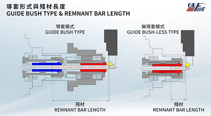
- Guide bushing-less kit available upon request for machining short parts. Ground bar stock is not required and reducing the remaining bar length.
- Additional deep face hole drilling post (2 drills) is attached to the back spindle. Max. drilling depth is up to 100 mm. Besides, these 2 drills can be adapted to driven drills as option for off-center drilling and tapping.
- Direct C-axis indexing helps reducing the spindle indexing time by avoiding to return to reference point when indexing is done from spindle rotating state.
- Thread whirling head or hobbing head can be mounted on the right cross tool post for processing bone screws or gear hobbing.
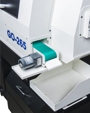
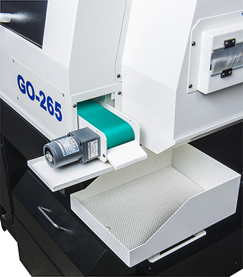
- The large chip tray is perfect for long-time operation. It is also possible to take out the products out and remove the chips during machining operations.
- Workpiece conveyor is standard. The workpiece is discharged from the back spindle to the workpiece conveyor, moving then to the workpiece container.
- Model GO-325 uses hydraulic cylinder for clamping the bar to be machined, ensuring no bar shrinkage during machining.

Higher rigid
- Increase rigidity of main spindle・s tool posts and feed axis sliding guide without affecting tooling accuracy, even for variable load cutting.
- Based on thermal physics, the main and back headstocks on X axes (X1, X2) are all mounted horizontally, reducing the heat-induced deformation to a minimum.
Optional tool spindles for right cross tool post
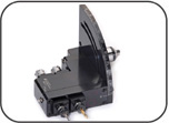
Bevel drilling head
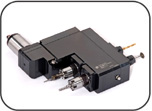
End-working tool spindle
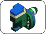
Hobbing
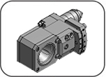
Whirling thread head
Back tool spindle
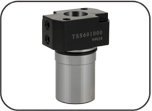
Adaptor for fixed tool
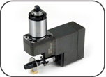
Back cross tool spindle
-
-
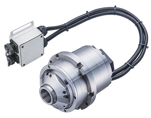
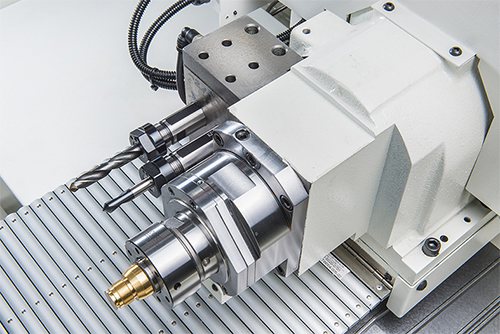
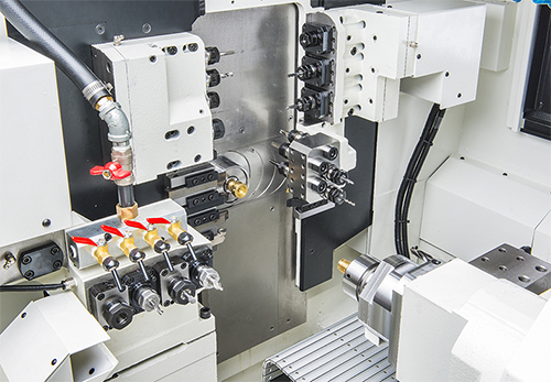
- More cross tools (7 in total)
- Cartridge type design for tool spindle (Right cross tool and back tool)
- Available to be equipped with other different tool spindle or fixed tool adaptor
- Wider choices for tooling layout
Higher rigid
- Increase rigidity of main spindle’s tool posts and feed axis sliding guide without affecting tooling accuracy, even for variable load cutting.
- Based on thermal physics, the main and back headstocks on X axes (X1, X2) are all mounted horizontally, reducing the heat-induced deformation to a minimum.
